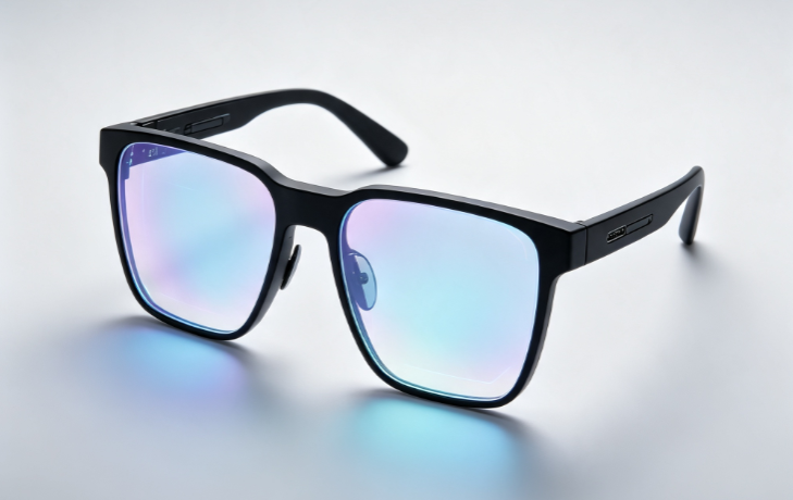
Following the landmark unveilings of the Apple Vision Pro and Meta’s Orion prototype, a decisive industry consensus has emerged across the global tech sector: the near-eye display (NED) optical engine is the primary make-or-break bottleneck determining whether AR/MR hardware can transition into mainstream consumer electronics [1].
According to industry data from Yole Intelligence’s 2026 Microdisplay Market Report, the global near-eye microdisplay market is projected to surpass $4.5 billion by 2030, expanding at a compound annual growth rate (CAGR) exceeding 32% [2]. However, engineering an all-day, eyeglass-style form factor weighing under 70 grams—while simultaneously delivering sunlight-readable peak brightness, rich color immersion, and extended battery life—remains a monumental technical hurdle.
“Building a real pair of AR glasses is one of the hardest hardware engineering challenges of our time. You have to pack the compute of a supercomputer, a display engine producing hundreds of thousands of nits, and full spatial awareness into a frame just a few millimeters thick.”
— Mark Zuckerberg, CEO of Meta [3]
As renowned AR optics analyst Karl Guttag has repeatedly emphasized, mainstream diffractive waveguide optics exhibit an end-to-end light transmission efficiency of less than 1% [4]. Constrained by this physical bottleneck, the display and semiconductor supply chains have coalesced around four primary technological camps: mature LCoS (Liquid Crystal on Silicon), rapidly commercializing Micro-OLED on Silicon (OLEDoS), the long-term endgame MicroLED (Inorganic Micro Light-Emitting Diode), and focus-free LBS (Laser Beam Scanning).
Below is an in-depth analysis of the technical architectures, physical trade-offs, and commercial trajectories of these four core technologies.
Core Technical Parameters Comparison
| Evaluation Metric | LCoS (Liquid Crystal on Silicon) | Micro-OLED on Silicon (OLEDoS) | MicroLED (Inorganic Micro-LED) | LBS (Laser Beam Scanning) |
| Emission Mechanism | Passive modulation (requires external light engine) | Self-emissive (organic diode) | Self-emissive (inorganic diode) | Flying-spot scanning (RGB Laser + MEMS) |
| Panel / Engine Brightness | High | Moderate (1,000 – 15,000 nits) | Extremely High | High |
| Contrast Ratio | Low (1,000:1) | Ultra-High (> 100,000:1) | Ultra-High (> 100,000:1) | High ( 10,000:1) |
| Response Time | Slow | Ultra-Fast | Ultra-Fast | Ultra-Fast (governed by MEMS frequency) |
| Light Engine Volume | Bulkier (requires PBS and dedicated light source) | Highly Compact (no external light source needed) | Extremely Compact (no external light source needed) | Extremely Compact (simplified projection optics) |
| Full-Color Maturity | High (mature semiconductor & LCD supply chains) | High (broad commercial adoption) | Low (challenges in red efficiency & full-color integration) | Moderate (RGB beam combining & speckle mitigation) |
| Primary Bottlenecks | Engine volume miniaturization, limited black-state contrast | Peak luminance headroom insufficient for lossy waveguides | Mass transfer yield, severe efficiency drop in micro-red LEDs | Laser speckle artifacts, resolution capped by MEMS frequency |
| Representative Devices | HoloLens 1, Magic Leap 1 [4, 5] | Apple Vision Pro, XREAL Air series, Rokid [1, 6] | Meta Orion prototype, RayNeo X2 [3, 7] | HoloLens 2, Bosch Smartglasses [8, 9] |
Architectural Deep Dive: The Four Technical Routes
1. LCoS (Liquid Crystal on Silicon)
- Working Principle: A liquid crystal layer is sandwiched between an upper glass substrate and a single-crystal silicon CMOS backplane. The CMOS circuit controls the voltage across each pixel to twist the liquid crystal molecules, modulating light reflected from an external illumination source [5].
- Key Advantages:
- Mature Manufacturing: Leverages standard silicon CMOS and established LCD fabrication infrastructure, yielding high pixel density (PPI) at a manageable cost structure.
- High Luminance Capability: Because it relies on an external high-power light source (LED or laser), it can deliver high output brightness. Consequently, it served as the go-to solution for early-generation AR hardware, such as Microsoft HoloLens 1 and Magic Leap 1 [4, 5].
- Primary Limitations:
- Bulky Optical Engine: LCoS optics require an external illuminator, a Polarizing Beam Splitter (PBS) cube, and the reflective chip itself. Packing these components into an eyeglass temple creates an oversized module, driving total headset weight well above 500 grams (e.g., HoloLens 1 weighed 579 g[5]. It fails to meet the weight envelope (< 75 g) demanded by modern consumer-grade AR glasses.
- Elevated Black-Level Leakage: Because liquid crystal layers cannot fully block background illumination, light bleeds through dark pixels. Virtual 3D assets appear encased in a faint, glowing gray “bounding box,” breaking spatial realism and visual immersion.

2. Micro-OLED on Silicon (OLEDoS)
- Working Principle: Organic light-emitting materials are sub-pixel deposited via vacuum thermal evaporation directly onto a single-crystal silicon CMOS driver backplane, blending semiconductor precision with OLED image quality [6].
- Key Advantages:
- Uncompromising Visual Quality: Delivers true blacks (infinite contrast), ultra-wide color gamut coverage, and microsecond-level pixel response times that eliminate motion blur.
- Form-Factor Efficiency: As a self-emissive display, it eliminates backlight units, significantly reducing overall light engine footprint—making it the dominant display engine for current spatial computing devices [1].
- Primary Limitations:
- Severe Waveguide Photonic Penalty: Even advanced tandem-stacked OLED architectures pushing panel brightness up to 10,000 – 15,000 nits struggle when paired with diffractive waveguides [6].
- The 1% Throughput Problem: With a 1% optical transmission efficiency, a 10,000-nit Micro-OLED screen delivers roughly 100 nits to the eye. Compared to ambient daylight (10,000 – 30,000 nits), the virtual overlay appears washed out. Overdriving organic materials to higher luminance triggers catastrophic thermal dissipation and accelerated permanent burn-in [6].

3. MicroLED (Inorganic Micro Light-Emitting Diode)
- Working Principle: Arrays of microscopic inorganic LED chips are mass-transferred or monolithically integrated onto a CMOS backplane [7]. It is widely regarded as the ultimate display engine for see-through optical waveguide AR glasses.
- Key Advantages:
- Unrivaled Peak Luminance: Green MicroLED panels can exceed millions of nits in raw output [7]. Functioning like a miniaturized spotlight, even after a 99% waveguide transmission loss, the remaining 1% light budget easily cuts through bright ambient sunlight.
- Robust Inorganic Reliability: Gallium Nitride (GaN) and related inorganic crystal structures tolerate thermal strain, resist humidity degradation, exhibit zero burn-in risk, and feature nanosecond switching speeds.
- Primary Limitations:
- The “Micro-Red” Efficiency Drop: As inorganic red LED die sizes shrink below 10um, sidewall defect density dramatically increases non-radiative recombination. The Internal Quantum Efficiency (IQE) drops drastically, converting electrical energy into heat rather than light [7, 8].
- Monolithic Full-Color Integration: Achieving a native RGB single-chip display at high yield remains a formidable manufacturing barrier. Alternate routes—such as Quantum Dot (QD) color conversion or optical prism combining—introduce efficiency penalties or physical volume bloat [8].
4. LBS (Laser Beam Scanning)
- Working Principle: Collimated beams from red, green, and blue semiconductor laser diodes are combined into a single ray and dynamically steered by a 2D MEMS (Micro-Electro-Mechanical Systems) mirror, projecting pixels directly into the user’s eye or optical waveguide in a raster-scan pattern [8, 9].
- Key Advantages:
- Infinite Depth of Field: The scanned image remains inherently in focus across varying projection distances without manual or active focus optics.
- High Energy Efficiency: Energy is expended only when drawing active pixels; displaying true black consumes zero light engine power.
- Primary Limitations:
- Laser Speckle Artifacts: High optical coherence creates granular interference patterns (speckle) on the screen, causing visual fatigue over extended viewing sessions [9].
- Resolution Hardware Ceiling: Display resolution is bounded by the mechanical resonant frequency and tilt angle of the microscopic MEMS mirror. Achieving higher resolutions demands higher-frequency mirror oscillations, pushing component costs and manufacturing difficulty up steeply [9].
Form Factor & System Architecture Alignment
The optical requirements across the XR spectrum have driven a clear division in display engine selection:

- Immersive VR / MR Headsets: Micro-OLED on Silicon is the preferred choice [1]. Enclosed optical paths shield ambient light, reducing peak luminance requirements while prioritizing high pixel density, wide color gamut, and pitch-black levels.
- Media-Consumption AR (Birdbath / Freeform):Micro-OLED on Silicon dominates this category [6]. Because Birdbath optics maintain higher efficiency (10% – 15%), a 5,000 – 10,000-nit panel provides adequate brightness for indoor use and video playback.
- All-Day Outdoor AR Glasses (Diffractive Waveguide): MicroLED is the target solution [3, 7]. The severe light loss of diffractive waveguides requires multi-hundred-thousand-nit panel engines. Until full-color MicroLED reaches mass-production yields, legacy LCoS and LBS remain functional transitional alternatives [4, 9].
References
- Apple Inc., “Apple Vision Pro Architecture and Spatial Display Engineering,” Apple Technical Publications, 2024.
- Yole Group, Microdisplay Market and Technology Report 2026, Yole Intelligence, 2026.
- M. Zuckerberg, “Keynote Address on Spatial Computing and Orion AR Architecture,” Meta Connect Proceedings, 2024.
- K. Guttag, “Waveguide Efficiency and Light Engine Constraints in Near-Eye Displays,” KGOnTech Display Insights, 2023.
- Microsoft Corp., “HoloLens Optical System Design and LCoS Light Engine Architecture,” Microsoft Research, 2018.
- C. L. Lin et al., “High-Luminance Tandem OLED Microdisplays on Silicon for Augmented Reality,” IEEE Transactions on Electron Devices, vol. 71, no. 3, pp. 1420–1427, 2024.
- E. Jang et al., “MicroLED Displays: Key Challenges in Sub-10 µm Red Efficiency and Mass Transfer Integration,” Nature Photonics, vol. 17, pp. 832–841, 2023.
- MicroLED Industry Association, MicroLED Commercialization Roadmap & Colorization Strategies, White Paper, 2025.
- Bosch Sensortec, “MEMS-Based Laser Beam Scanning for Ultra-Lightweight Smartglasses,” SPIE AR/VR/MR Proceedings, vol. 12010, 2022.
Disclaimer
This document is provided strictly for educational, analytical, and informational purposes. The technical data, physical parameters, market forecasts, and architectural trade-offs referenced herein are derived from publicly available academic research, industry whitepapers, and semiconductor disclosures as of 2026. Reference to specific commercial entities, trademarked brands, or proprietary hardware architectures (e.g., Apple Vision Pro, Meta Orion, HoloLens) does not constitute an endorsement, commercial sponsorship, or financial/investment advice.